
Titan 440XC Airless Paint Sprayer Parts
Find repair parts for the Titan 440 XC using owner manual 313-1434 Rev B (0101). This manual covers models 700-2000 (120V complete). Match your sprayer model, voltage, and configuration before ordering.
Click a numbered marker to see matching OEM and aftermarket replacement choices. Use the zoom buttons to enlarge a drawing.
Jump to: Main Assembly Overview · Motor Assembly · Gear Box Assembly · Fluid Section / Pump · Suction Set Assembly · Filter Block Assembly · Stand / Skid Assembly
Main Assembly Overview
Unnumbered exploded overview. Use the separate numbered assembly diagrams below to select parts.
No confirmed catalog match: Item Label - 700-1015 Replacement label (not shown in overview); Item Label - 313-175 Replacement label (not shown in overview); Item Label - 313-1432 Replacement label (not shown in overview).
Motor Assembly
Motor kit 700-070 includes items 3-6, 8, 9, and 10. The motor housing/field at item 8 and armature at item 10 have no separate part numbers in this manual. Screw item 3 appears twice.
No confirmed catalog match: Item 1 - 700-716 Screws, 1/4 x 1”; Item 2 - 700-128 Rear cover w/label; Item 3 - 700-063 Screws, 8/16 x 3/4”; Item 4 - 700-632 End cap; Item 7 - 700-766 Screws 8-32 UN x 1.125; Item 11 - 700-070 Motor Kit Complete (includes items 3–6,8,9, and 10).
Gear Box Assembly
For the 440 XC. Screw 730-260 appears at both callouts marked 31. The front-plate entry 32 repeats front-cover label number 700-1015, so the plate is left unlinked pending confirmation.
No confirmed catalog match: Item 5 - 700-551 Wire tube; Item 6 - 704-044 O-ring; Item 7 - 700-650 Power cord (includes items 8, 9, and 10).1; Item 8 - 700-778 Cord grip nut; Item 9 - 700-779 Washer; Item 10 - 700-789 Grommet; Item 11 - 700-777 Housing; Item 13 - 700-161 Pressure control board; Item 19 - 700-645 Rubber boot; Item 20 - 700-511 Thrust washer; Item 21 - 700-732 Pinion gear; Item 22 - 704-083 Gear box housing; Item 24 - 700-593 Thrust washer; Item 25 - 765-067 Output pinion gear; Item 29 - 700-739 Pump housing; Item 32 - 700-1015 Front plate (manual repeats the front cover label number; confirm correct plate before ordering).
Fluid Section / Pump
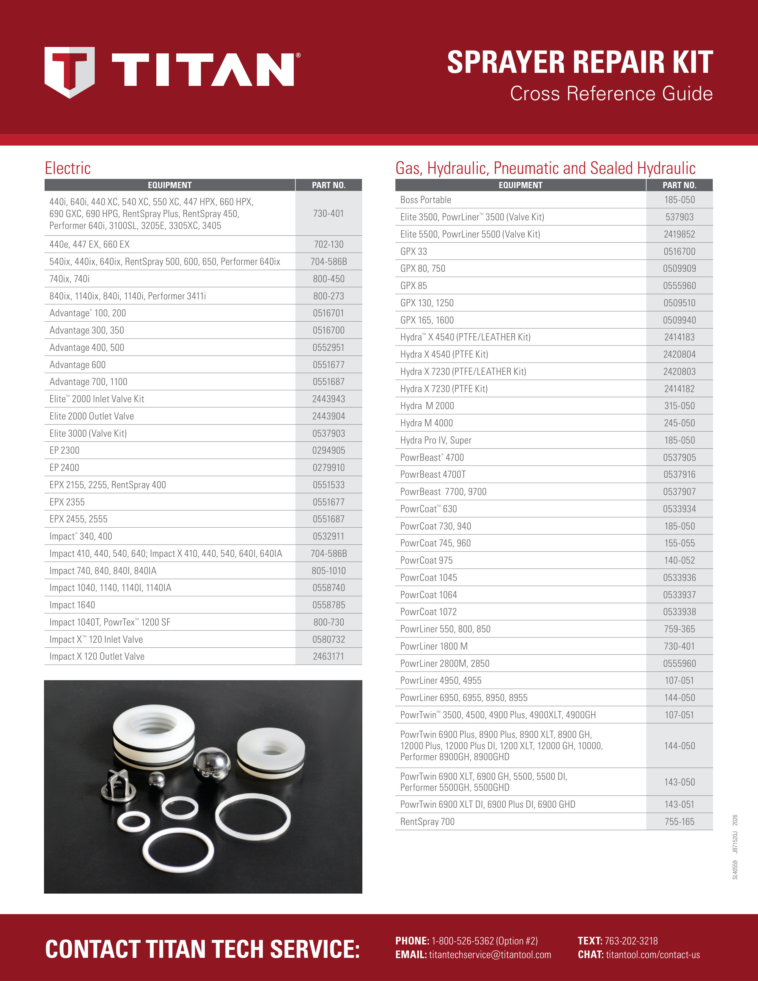
Fluid section 730-535 includes items 2-5 and 7-21. Piston assembly 704-090 includes the piston and outlet-valve components. Repacking kit 730-401 and packing tool 762-202 are also listed. Follow the packing orientation shown.
No confirmed catalog match: Item 1 - 700-735 Crank and slide connecting rod assy; Item 4 - 700-603 Upper packings; Item 15 - 730-509 Bushing; Item 17 - 730-510 Cage; Item 22 - 704-090 Piston assembly; Item 24 - 730-535 Fluid section complete (includes items 2, 3, 4, 5 ,and 7–21).
Suction Set Assembly
For complete siphon assembly 700-1025. Siphon hose 700-1023 includes items 2, 3, and 6. O-ring item 2 includes the standard and optional solvent-resistant versions.
No confirmed catalog match: Item 5 - 755-135 Clip.
Filter Block Assembly
Filter block assembly 700-624 excludes items 18, 20, 23, and 27. Valve assembly 700-258 is item 29. Item 8 includes the standard Viton and optional PTFE O-rings. The manual-listed bypass O-ring tool is not pictured.
No confirmed catalog match: Item 1 - 700-421 Filter housing; Item 7 - 700-246 Valve housing; Item 17 - 700-588 Filter block; Item 18 - 700-494 Outlet mounting bolt; Item 22 - 700-621 Pipe plug; Item 30 - 700-624 Filter Block Assy. (excludes items 18, 20, 23, and 27).
Stand / Skid Assembly
Left leg 704-092 includes items 2 and 4. Right leg 704-091 includes items 2, 5, and 6.